Best of Malaysia
qpstransformers.com
electrical equipment maintenance, energy efficiency transformers, Klang Valley industry, MS IEC 60076 compliance, power load calculation, power transformer basics, QPS Transformers Malaysia, transformer installation guide, transformer testing procedures, voltage regulation solutions
Best
0 Comments
Power Transformer Guide: QPS Transformers Solutions in Klang Valley, Malaysia
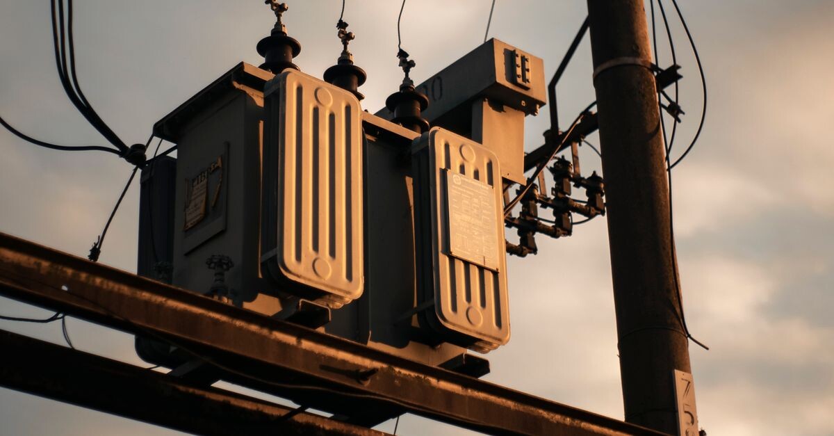
What is a power transformer and how does it work?
A power transformer is a static device that transfers electrical energy between circuits via electromagnetic induction, changing voltage while keeping frequency constant. It consists of primary and secondary windings around a laminated steel core, enabling step‑up or step‑down of voltage for efficient power transmission and distribution.
Power transformers are essential in transmission networks, stepping up voltage for efficient long-distance transport and stepping it down for safe distribution to factories, commercial buildings, and residences. In the Klang Valley, they support the manufacturing sector, data centres, and infrastructure projects by ensuring stable voltage supply.
- Core: laminated silicon steel, low‑reluctance path for magnetic flux.
- Windings: copper or aluminum, insulated with enamel or paper.
- Tank: houses the assembly and insulating oil.
- Conservator: accommodates oil expansion.
- Breather: contains silica gel to absorb moisture.
- Bushings: provide insulated connections to external circuits.
- Tap changer: enables on‑load voltage regulation.
Core components of a power transformer
The main components of a power transformer are the magnetic core, primary and secondary windings, tank, conservator, breather, bushings, and tap changer. The core provides a low‑reluctance path for flux; windings carry current; the tank holds insulating oil; accessories manage oil expansion, moisture, and voltage regulation.
- Magnetic core – grain‑oriented silicon steel laminations.
- Primary and secondary windings – copper or aluminum, insulated.
- Steel tank – contains insulating oil and provides mechanical protection.
- Conservator tank – allows oil volume change with temperature.
- Breather – silica gel cartridge to dry incoming air.
- Bushings – porcelain or epoxy insulators for HV/LV connections.
- Tap changer – off‑load or on‑load mechanism to adjust voltage ratio.
Operating principle (step-up/step-down)
When AC voltage energizes the primary winding, it creates a varying magnetic flux in the core, which induces a voltage in the secondary winding proportional to the turns ratio. More secondary turns step up voltage; fewer turns step it down, while tap changers allow on‑load voltage regulation.
- Turns ratio (N_s/N_p) determines voltage transformation.
- Vector group defines phase shift between primary and secondary.
- On‑load tap changer (OLTC) adjusts taps without de‑energising.
- Off‑load tap changer requires de‑energising for adjustment.
- Impedance influences fault current and voltage regulation.
Why choose QPS Transformers in Klang Valley for your power transformer needs?
QPS Transformers offers locally manufactured power transformers that meet international IEC standards and Malaysian MS IEC 60076, reducing lead times and ensuring prompt technical support. Their Klang Valley facility provides custom designs, rapid response, and compliance with local regulations, making them a reliable partner for industrial projects.
Local expertise and manufacturing capabilities
QPS Transformers operates a modern fabrication plant in Klang Valley equipped with CNC winding machines, vacuum impregnation units, and IEC‑compliant testing bays. Their engineering team delivers custom designs up to 150 kV and 50 MVA, performing impulse, temperature‑rise, and short‑circuit tests to guarantee performance.
- CNC winding machines for precise coil formation.
- Vacuum impregnation removes air bubbles from insulation.
- Testing bays for impulse, temperature‑rise, short‑circuit, and dielectric tests.
- Engineering support for custom specifications and load profiling.
- Compliance with MS IEC 60076, IEC, and local grid codes.
Certifications and compliance with Malaysian standards
The company holds ISO 9001:2015 for quality management and ISO 14001:2015 for environmental management, plus SIRIM QAS approval under MS IEC 60076. Every unit undergoes full‑type testing—including temperature rise, short‑circuit, and insulation resistance—before dispatch, ensuring local and international conformity.
- ISO 9001:2015 – quality management system certification.
- ISO 14001:2015 – environmental management system certification.
- SIRIM QAS – product conformity to MS IEC 60076.
- Routine tests: temperature rise, short‑circuit, insulation resistance.
- Type tests performed on prototype units for design validation.
Key specifications and standards for power transformers in Malaysia
In Malaysia, power transformers must comply with MS IEC 60076, which defines voltage classes, power ratings, temperature rise, insulation levels, and test procedures. Typical units range from 1 MVA to 500 MVA, with efficiencies above 99.5 % and impedance between 4 % and 10 % depending on rating.
Voltage ratings and capacity ranges
Voltage ratings are grouped as distribution (≤33 kV), sub‑transmission (33‑132 kV), and transmission (>132 kV). Corresponding capacities span from ~50 kVA for small distribution units to over 200 MVA for large grid interconnections, matching the load profiles of residential, industrial, and transmission networks in the Klang Valley.
- Distribution transformers: 50 kVA – 2 MVA, ≤33 kV.
- Sub‑transmission: 2 MVA – 20 MVA, 33‑132 kV.
- Transmission: >20 MVA, >132 kV.
- Standard kVA steps: 50, 63, 80, 100, 125, 160, 200, 250, 315, 400, 500, 630, 800, 1000 kVA etc.
- Custom ratings available upon request.
Efficiency losses and temperature rise limits
Losses are split into no‑load (core) and load (copper) components, with MS IEC 60076 setting maximum values based on rating. For oil‑immersed units, winding temperature rise is limited to 65 °C and top‑oil rise to 60 °C, ensuring safe continuous operation under typical ambient conditions.
- No‑load loss (P0) – hysteresis and eddy‑current losses in core.
- Load loss (Pk) – I²R losses in windings.
- Total loss = P0 + Pk.
- Efficiency = (Output / (Output + Losses)) × 100 %.
- Temperature rise limits protect insulation life and safety.
How to select the right power transformer for industrial applications in Klang Valley
Selecting a transformer starts with calculating the maximum demand load, applying a diversity factor, and adding spare capacity for future growth. Environmental factors such as humidity, temperature, and altitude must be considered to ensure proper cooling, insulation, and compliance with local safety regulations.
Load calculation and future expansion considerations
Begin by summing the rated power of all equipment, apply a demand factor (typically 0.8 for industrial plants), then add 10‑20 % spare capacity for anticipated growth. For motors, use a diversity factor of 0.75 and add 15 % spare before selecting the nearest standard kVA rating from the manufacturer’s catalogue.
- List all equipment and note their kVA ratings.
- Sum the ratings to obtain the connected load.
- Apply diversity factor (0.75‑0.9) based on simultaneity.
- Add 10‑20 % spare for future expansion.
- Select the next standard kVA size offered by QPS Transformers.
- Verify short‑circuit capability and impedance.
Environmental factors (humidity, temperature, altitude)
Klang Valley’s tropical climate brings 80‑90 % humidity and ambient temperatures up to 35 °C, which affect cooling and insulation aging; installations above 500 m require capacity derating due to lower air density. Use weatherproof IP55 enclosures outdoors and ventilation louvers indoors to mitigate these effects.
- High humidity reduces dielectric strength of oil and increases corrosion risk.
- Elevated temperature accelerates insulation ageing (Arrhenius law).
- Altitude >500 m lowers cooling efficiency; apply derating factor.
- Outdoor units: IP55 rated enclosure, raised plinth, proper drainage.
- Indoor units: louvers or forced airflow to maintain ambient temperature.
- Regular cleaning of bushings and radiators prevents overheating.
Installation and maintenance best practices for power transformers
Proper installation involves site preparation, foundation levelling, oil filling, and vacuum drying to remove moisture, followed by energisation and testing. Maintenance includes regular visual inspections, oil analysis (dielectric strength, DGA), thermographic scanning, and periodic electrical tests such as turns ratio and insulation resistance.
Pre-installation site checks
Before placement, verify that the foundation can support the transformer’s weight, ensure adequate clearance for cooling airflow, and confirm that grounding electrodes meet MS IEC 62305 standards. Check for flood risk, provide drainage, and level the foundation to withstand seismic activity per MS 1383.
- Foundation design: reinforced concrete, load‑bearing capacity ≥ transformer weight + 20 %.
- Clearance: minimum 1.5 m horizontal, 2.5 m vertical for outdoor units.
- Grounding: earth electrode resistance < 1 Ω, bonded to facility ground.
- Drainage: slope away from transformer, French drain or sump.
- Seismic restraints: follow MS 1383 guidelines for bolted base plates.
Routine testing and oil analysis
Schedule dissolved gas analysis (DGA) annually—or semi‑annually for heavily loaded units—and measure dielectric breakdown voltage every six months. Perform winding resistance and insulation resistance tests during shutdowns, comparing results to baseline values to track transformer health over time under normal operating conditions.
- DGA: detect gases like H2, CH4, C2H2, CO, CO2 indicating faults.
- Dielectric strength: BDV test per IEC 60156, limit > 30 kV for 2 mm gap.
- Winding resistance: measure each winding, compare to manufacturer’s values.
- Insulation resistance: megger test, typical > 1 GΩ at 500 V DC.
- Thermographic scan: identify hot spots on tank and bushings.
- Record ambient temperature, load, and oil temperature at each test.
Frequently Asked Questions about Power Transformers in Klang Valley
What is the typical lead time for a custom power transformer from QPS Transformers in Klang Valley?
Lead times typically range from 8 to 12 weeks for standard designs, depending on complexity and production schedule, and include design approval, winding, assembly, testing, and final inspection. For urgent projects, QPS Transformers offers expedited service that can reduce delivery to 4–6 weeks with prior engineering approval.
How often should transformer oil be tested for dielectric strength and dissolved gases?
Dielectric strength testing should be performed every six months to detect moisture ingress or oil degradation that could compromise insulation. Dissolved gas analysis (DGA) is recommended annually, or semi‑annually for transformers operating under heavy load or in harsh environments, to identify early fault indicators such as overheating or arcing.
What safety clearances are required around a power transformer installed outdoors in Malaysia?
A minimum horizontal clearance of 1.5 metres from walls, fences, or other equipment is required to allow adequate airflow for cooling and safe access for maintenance. Vertical clearance above the transformer tank should be at least 2.5 metres to prevent contact with structures and to satisfy the safety distances stipulated in MS IEC 60076‑10 for outdoor installations.
Can QPS Transformers provide transformers that meet both MS IEC 60076 and international IEC standards?
Yes, QPS Transformers designs and manufactures units that comply with MS IEC 60076, which aligns closely with IEC 60076 standards, ensuring mutual recognition for both local and international projects. Their testing facilities are accredited to perform IEC standard tests, including temperature rise, short‑circuit, and impulse assessments, allowing seamless certification for export or multinational contracts.
What factors affect the efficiency of a power transformer under partial load conditions?
Under partial load, copper losses decrease with the square of the load current while core losses remain essentially constant, causing the efficiency curve to peak around 50‑70 % of rated capacity. Additional factors influencing efficiency include core material, winding configuration, operating temperature, and harmonic distortion from non‑linear loads that increase stray losses.
Share this content: